
Page 30 - CC 2019 ID Look Inside
P. 30
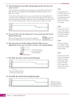
4.  Click the third point, press Shift, and drag right until the ruler shows the
                   cursor is at 6.5″.
                                                                                             Note:
                   As we just explained, the aff ected curve gets larger as you drag farther away from the
                   point. Because you’re dragging exactly horizontally, the horizontal segment on the   If you add points to a
                   right is not curving.                                                     curved line segment, the
                                                                                             new points automati-
                   On the left side of the point, however, you can see the eff ect of converting Point 3 to
                   a  symmetrical point. Dragging to the right side of the point adds direction handles on   cally adopt the necessary
                   both sides of the point; the length and position of the left handle defi nes the shape of the   direction handles to
                   curve on the left side of the point, which is the one you want to aff ect in this step.  maintain the original
                                                                                             curve shapes.


                                                                                             Note:

                                                                                             Th  e lines that connect
                                                                                             anchor points based on
                                                                                             the angle and length of
               5.  Choose the  Pen tool in the Tools panel. It is now nested under the Convert   the control handles are
                   Direction Point tool.                                                     called  Bézier curves.
                   When you choose a nested tool variation, the nested tool
                   becomes the default option in that position on the Tools panel.
                                                                                             Note:
               6.  Move the cursor over the left endpoint of the line. When you see a        When you drag direc-
                   diagonal line in the cursor icon, click to connect to the existing endpoint.  tion handles, the blue
                                                                                             lines preview the eff ects
                                                                                             of your changes.
                                                      This icon indicates that
                                                      clicking will connect to
                                                      the open endpoint.                     Note:
                                                                                             If you move an anchor
               7.  Press Shift, then click at the bottom-left bleed guide.                   point that has direction
                                                                                             handles, the handles
                                                                                             don’t change angle or
                                                                                             length. Th  e related
                                                                                             curves change shape
                                                                                             based on the new posi-
                                                                                             tion of the point.


                    Shift-click to create a vertical line
                    connected to the previous point.

               8.  Press Shift, then click the bottom-right bleed guide.


                                                                                   Shift-click to create a
                                                                                   horizontal line between
                                                                                   the previous point and
                                                                                   the point where you click.


           40     Project 1: Letterhead Design