


Page 56 - CS6_GD_Look_Inside.pdf
P. 56
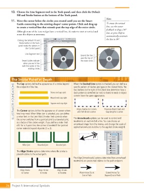
10.  Choose the Line Segment tool in the Tools panel, and then click the Default
                    Fill and Stroke button at the bottom of the Tools panel.
                                                                                             Note:
                11.  Move the cursor below the circles you created until you see the Smart
                    Guide connecting to the existing shapes’ center points. Click and drag up    To create the vertical
                    to create a vertical line that extends past the top edge of the outer circle.  line, use the cursor
                                                                                             feedback to drag a 90°
                    Although none of the icon wedges have a vertical line, it’s easier to start at vertical and   line, or press Shift to
                    rotate the objects as necessary.
                                                                                             automatically constrain
                                                                                             the line to 90°.
                     Clicking the Default Fill and
                      Stroke button in the Tools
                     panel resets the options in
                           the Control panel.

                           Line Segment tool
                                                                        Extend the line
                                                                        past the top of
                        Smart Guides indicate                           the outer circle.
                         when you are in line
                         with the center of the
                             existing circles.


                The Stroke Panel in Depth                          When the Dashed Line option is checked, you can define a
                    The Cap options define the appearance of a stroke beyond
                  ILLUSTRATOR FOUNDATIONS  The Corner options define the appearance of corners where   dash pattern is stretched (or not) so that line ends or object
                    the endpoint of the line.
                                                                   specific pattern of dashes and gaps in the related fields. The
                                                                   two buttons to the right of the check box determine how a
                                                None end cap style
                                                                   corners have the same appearance.
                                                Round end cap style

                                                Square end cap style

                                                                     Aligns Dashes to Corners
                                                                                            Preserves Exact Dash and
                                                                      and Path Ends is active
                                                                                             Gap Lengths is active
                    two lines meet. When Miter Join is selected, you can define
                    a miter limit in the Limit field. A miter limit controls when
                    the corner switches from a pointed joint to a beveled joint,
                                                                   treatments on each end of a line. You can choose an
                    as a factor of the stroke weight. If you define a miter limit   The Arrowheads options can be used to control end
                    of 2 for a 2-point line, the corner is beveled if the pointed   arrowhead shape from the menus, and change the scale of
                    corner extends beyond 4 points (2 1 2).        applied arrowheads (relative to the applied stroke weight).


                         Miter join  Rounded join   Beveled join


                    The Align Stroke options determine where the stroke is
                    placed relative to the actual path.
                                                                   The Align [Arrowheads] options determine how arrowhead
                                                                   treatments are positioned relative to the path endpoint.


                       Align Stroke   Align Stroke   Align Stroke
                        to Center      to Inside      to Outside        Place Arrow Tip at   Extend Arrow Tip
                                                                          End of Path       Beyond End of Path


           76 Project 1: International Symbols

